Cincinnati Lasers
Ballscrew guys have extensive on site field service experience on the Cincinnati CNC Lasers. We carry all of the essential bearing components to repair and accurize not only the ball screws, but the Linear Way Guide motions systems as well. The CL-5, CL-6, CL-7, and CL-7a all share a similar style and design. But the different models often have various types of ball screws. Commonly they are Japanese NSK systems. Often we find reground and shop refurbished screws. Or, like in CL-6 machines, STAR ball screws. Regardless, Ballscrew Guys has the experience in refurbishing the motion systems of CNC Laser systems. We also know of many aftermarket service and support technicians for all aspects of the Cincinnati Industrial Equipment. Call us, we can help!
What many Cincinnati owners and operators may not be aware of, is that Cincinnati actually has a test cutting part program specifically designed to evaluate whether or not your ball screws require service or refurbishment. We can send you this program, or direct you to make some simple cutting patterns and shapes, to help gauge the looseness and wear in your ball screws. Fill out our Ballscrew Guys contact form and we will be happy to assist you in diagnosing whether or not you need ball screw service. Free of charge.
While CL-5, CL-6, CL-7, and CL-7a Lasers are extremely stout and rugged, they have some common wear issues which appear after thousands of hours of production use. These being alignment and Y-Axis "square" issues, as mechanical positioning of the entire Y-Axis gantry is only controlled and kept fixed on one side of the machine. The single bearing system giving alignment of the entire X-Axis is one single Linear Way Guide Rail, with only two blocks or sliders moving across it. All mounted offset to one side on the machine, next to the ball screw. Because of the location of this critical CNC bearing system, any looseness or wear in the linear way guide blocks is amplified the closer the Y-Axis is moved towards the controller station. The simple way for an equipment owner/operator to test for this is to cut some 1/4" circles out of 14-16 gauge steel. Cut some where the material is positioned near where the ball screw is located, farthest away from the controller. Cut another sample of holes on the side closest to the controller. X-Axis Linear Way Guide looseness will be visible on the part of the controller side. Those holes have a wider out of round issue, in proportional alignment with the X-Axis than the ones cut closer to the ball screw. On really loose systems this is clearly visible by eye. But it's best proven by measuring out of roundness with a dial caliper.
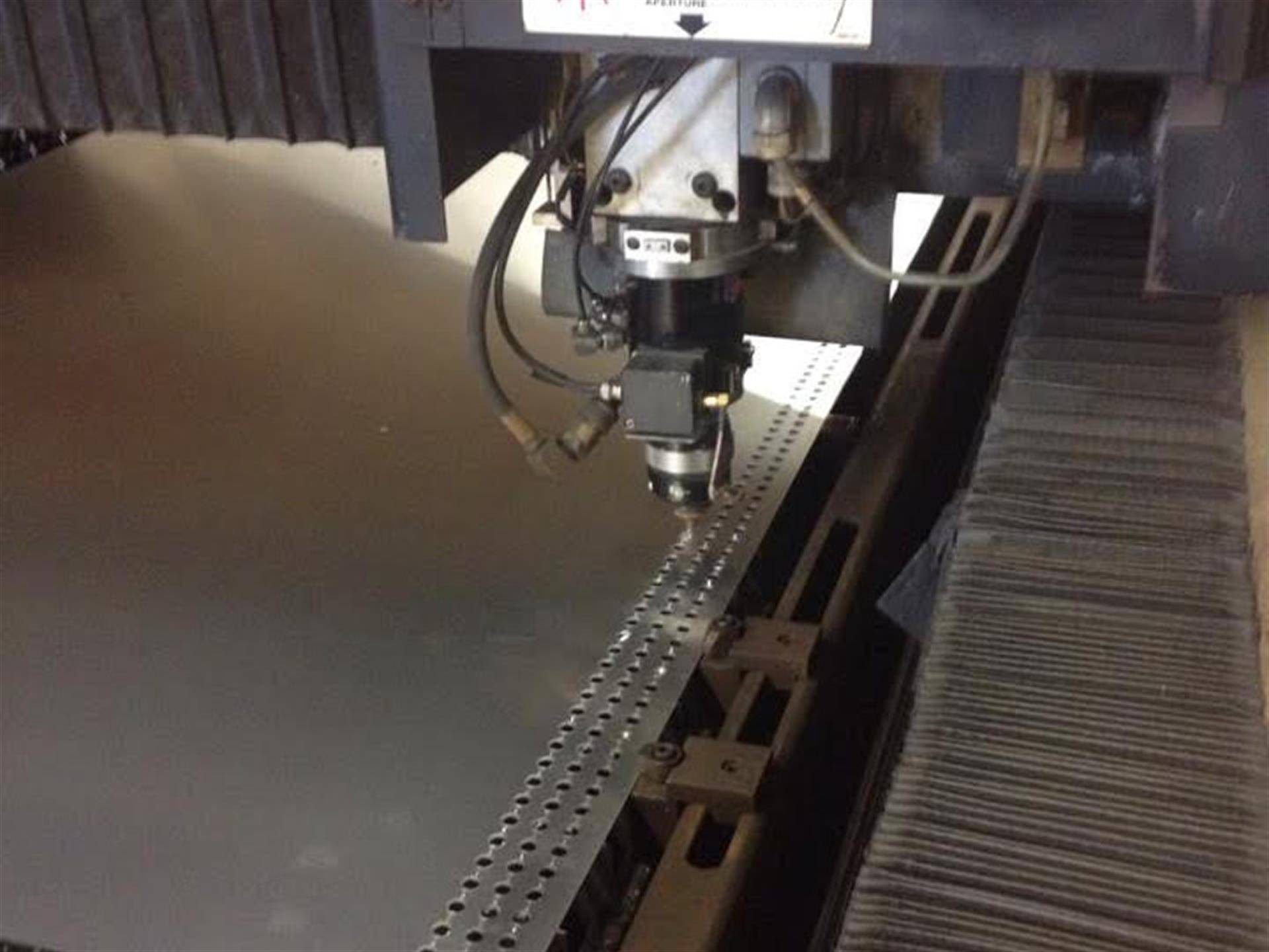
Here custom washer rings are being cut at high speeds out of aluminum. When you need to dial in your Cincinnati to return to like new accuracy and performance without paying OEM new ball screw prices, Call Us. We can make this happen at a fraction of the OEM cost AND without the down time.
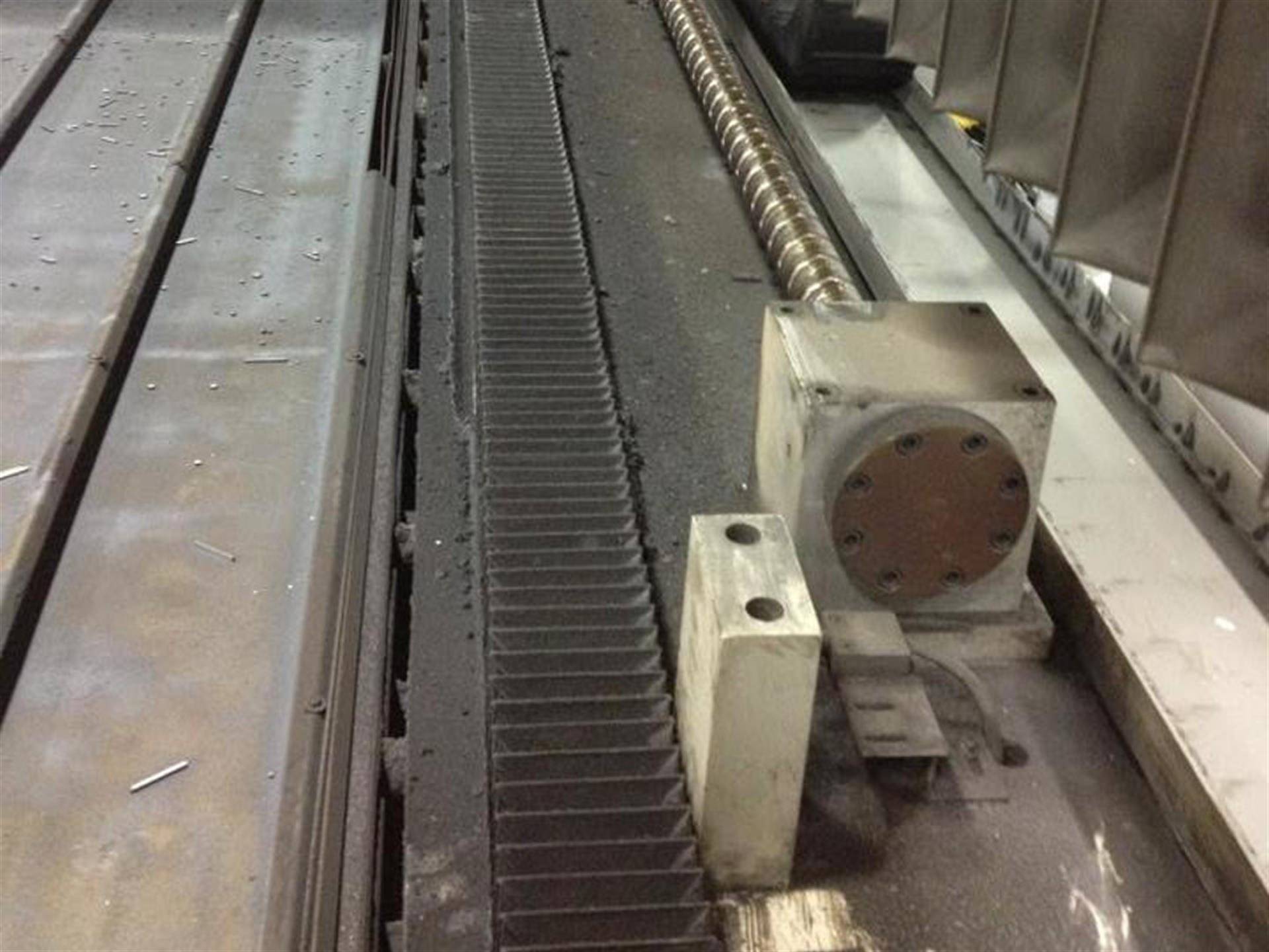
What the CL-5, CL-6, CL-7, and CL-7a X-axis area often looks like with the protective covered removed. This is the rather typical condition and dirtiness found in most machines. The X-Axis protective cover is taken off so we can work on the Ball Screw, Linear Motion System, inspect the limit switches, and evaluate the end bearing conditions of the Cincinnati End Bearings.
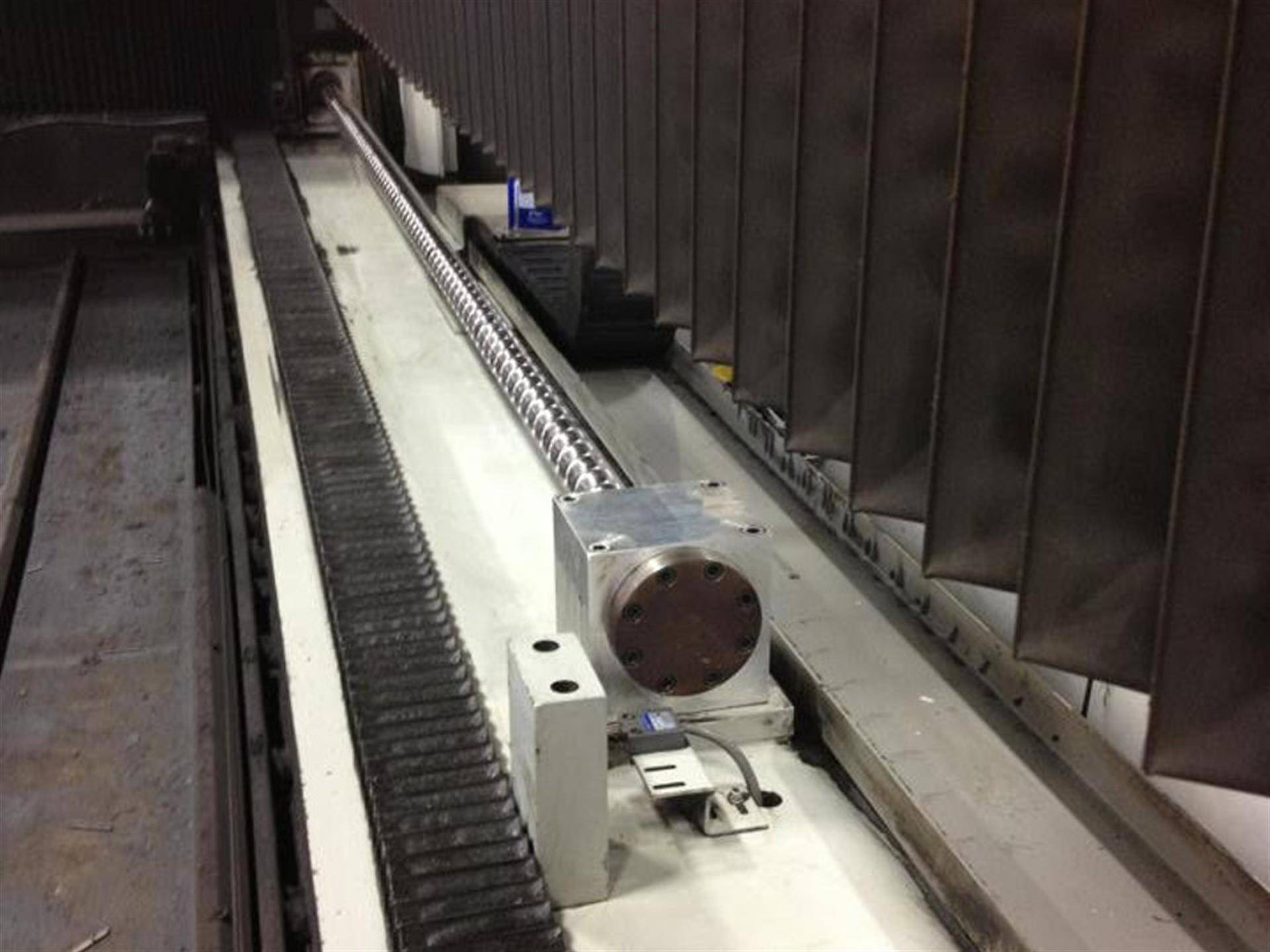
The After photo of the X-Axis area on a Cincinnati. The first step in completing a motion system inspection is removal of dirt and grease. Here the Linear Way Guide Rail Covers seem to be in great shape. Ballscrew Guys also clean and inspect the X-Axis limit switches on both ends of the machine. Making sure they aligned and grit free. Faulty limit switches can cause terrible motion systems crashes with the laser head gantry. Ballscrew Guys have responded to enough of these where cannot stress enough periodic cleaning and inspection.
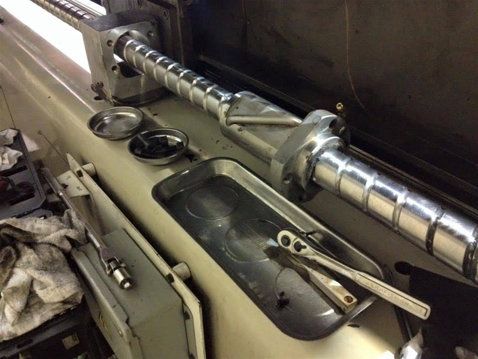
The X-Axis ball screw is disconnected from the Laser head gantry/yoke. The lubrication system is inspected and checked at this time, making sure it is making its way into the ball nut. The ball nut is disassembled, and raceways inspected. All parts are cleaned and lubricated. Then rebuilt with new larger sized bearings, custom fit to the existing ball nut and screw raceway wear. Restoring accuracy to the ball screw assembly, the oversized ball bearings eliminating backlash and deadband.
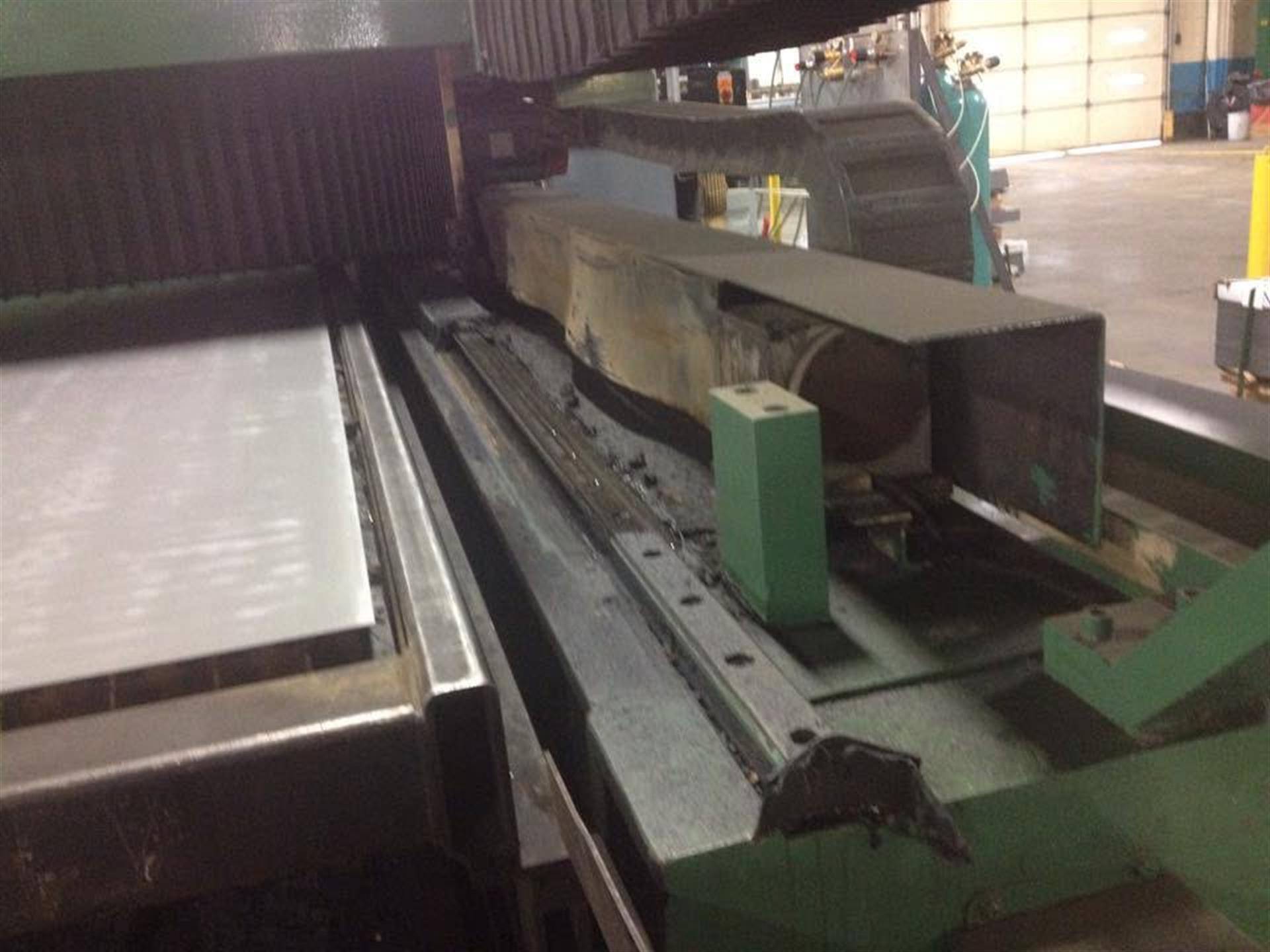
After refurbishment of the X-Axis ball screw, it is often also necessary to refurbish the X-Axis Linear Way Guide blocks. Also commonly referred to as "Skates" or "Sliders". If your Cincinnati CL-Series Laser has operated for a period of time with damaged covers like in this image, Linear Way Guide block service should be done. This is why we include this service as standard as part of our Cincinnati Flat Rate Specials.
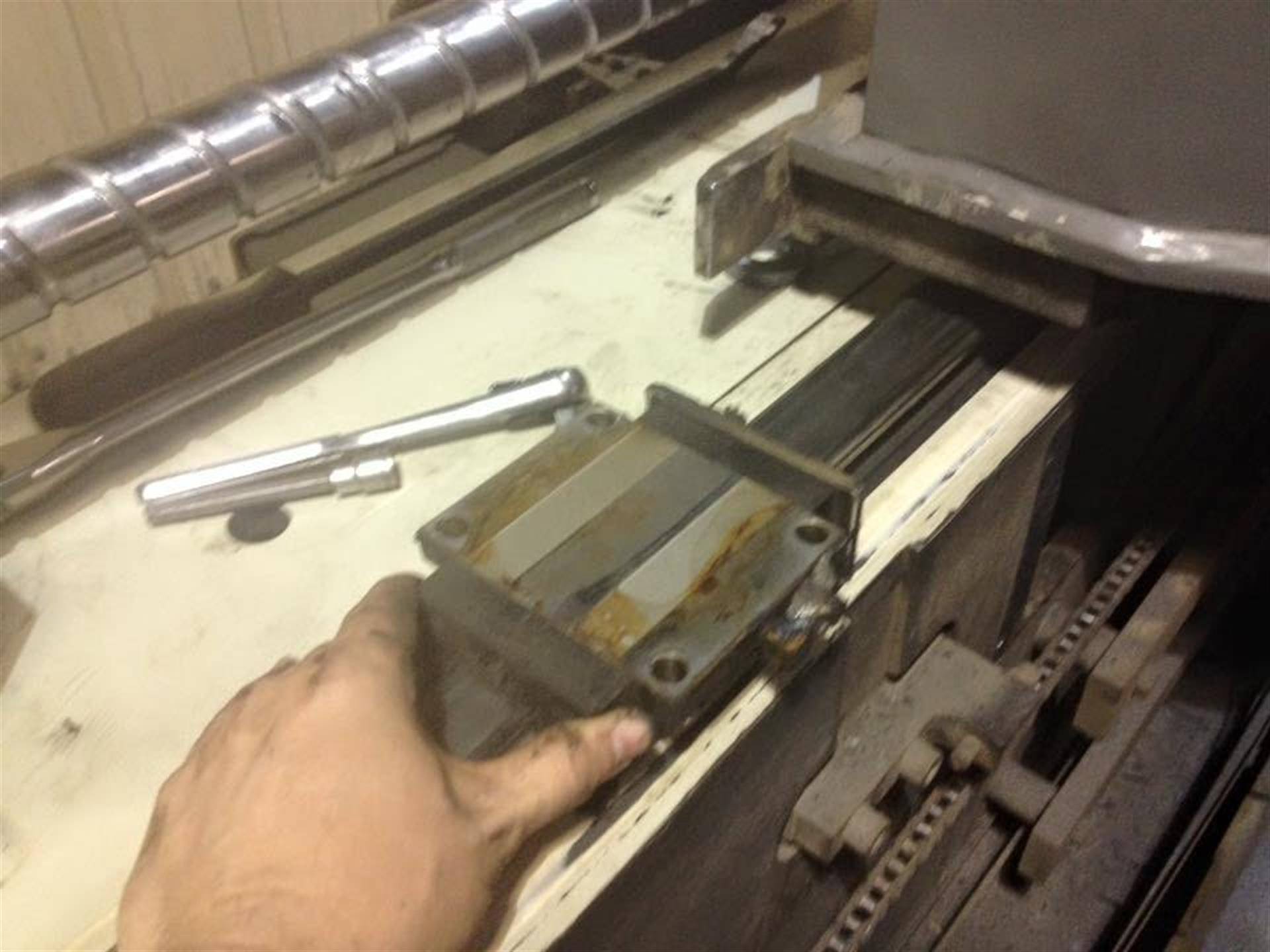
The Cincinnati CL-Series of Lasers positions the Y-Axis and Laser Gantry solely on one side of the machine. One Linear Way Guide Rail and ball screw is the core of accuracy in the Cincinnati X-Axis. If the ball bearings within the Linear Way Guide Blocks are worn down or clogged with debris, this will show clear signs of looseness or stuttering when cutting. The wiggle effect is then magnified the further out you cut, closer to the operator's console.
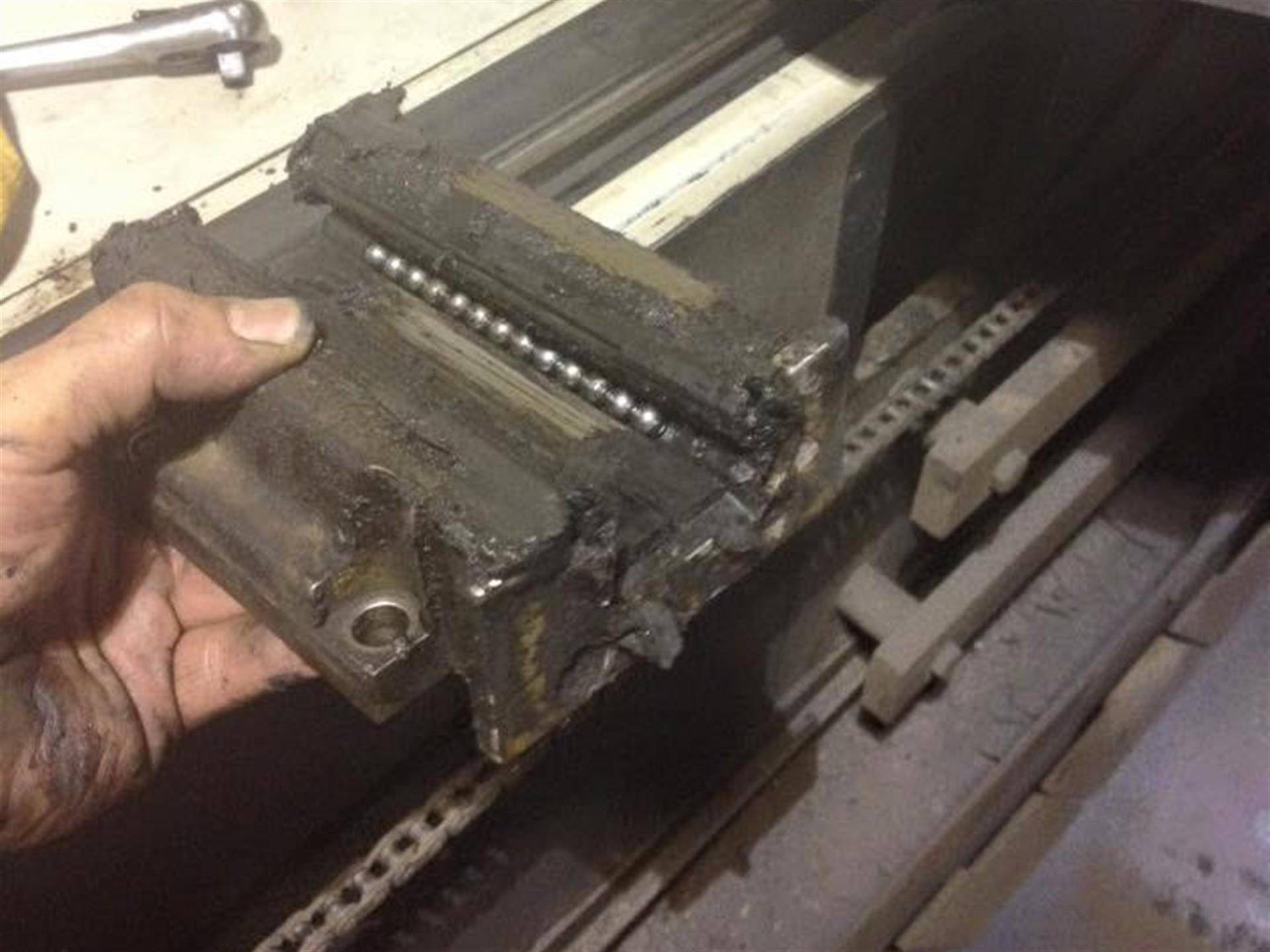
The Linear Way Guides are the first motion bearing system to get contaminated during cutting. The grease packs in with dirt and debris, wearing down the ball bearings in the guide blocks. Eventually the bearings stop rolling freely, starting to cause damage to the blocks and the rails they slide on. This is image shows what we commonly find when servicing the X-Axis linear way guide system. Cleaning, flushing out, installing oversized ball bearings and fresh grease does wonders for bringing the accuracy and cut quality of your Cincinnati CL-5, CL-6, CL-7, and CL-7a to like new again.
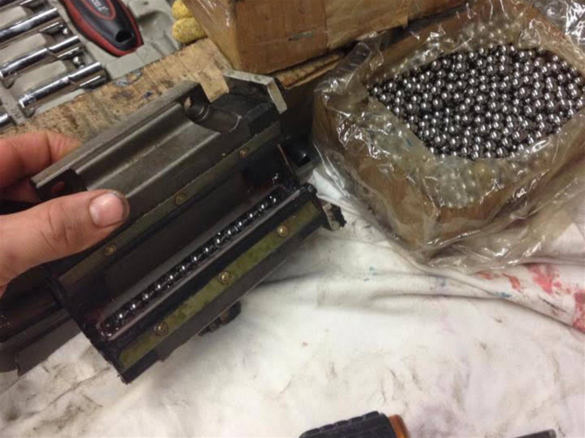
Most often, the Original Equipment Manufacturer states that looseness in the X-Axis Linear Way Guide system is only corrected by replacing the Linear Way Guide Blocks AND The Guide Rails they slide on. This is true, because simply buying new sliding blocks would still be loose on a worn rail. But it is extremely expensive.
However, we can restore accuracy to your X-Axis Linear Way Guide System by applying the same techniques used to refurbish the screw. Oversized machine tool grade ball bearings can be loaded into your bearing blocks matching the wear of the rail, restoring your existing parts to like new without the forced upgrade in parts and at a fraction of the price.
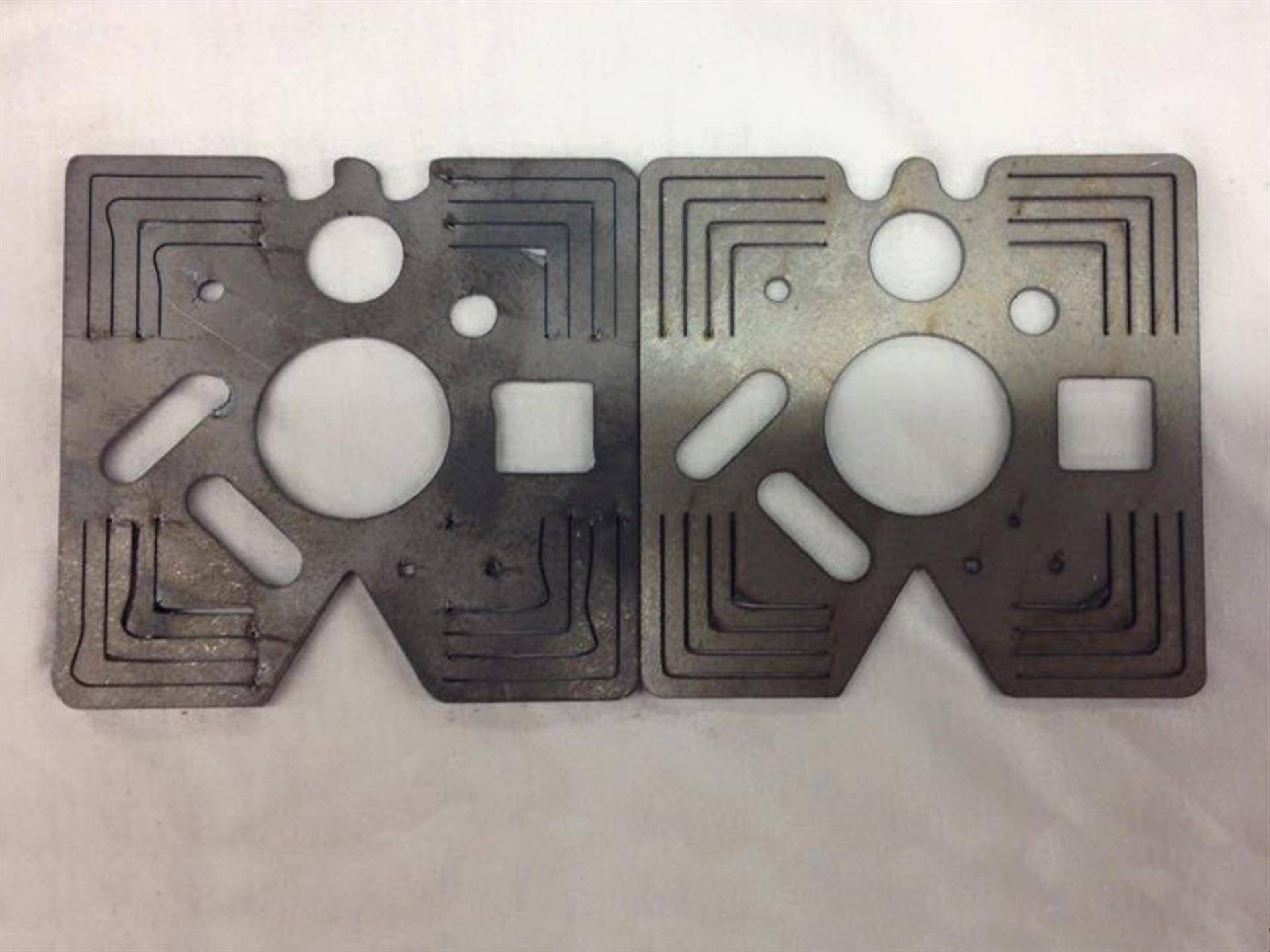
Above is before and after picture of parts cut on a Cincinnati CL-6 Laser in Greensboro, NC (02/03/16) accurized by Ball Screw Guys technicians. This part is Cincinnati's ball screw evaluation system, referred to as the "8019 Test Program". It is a specific series of cuts made in steel to detect and evaluate looseness in ball screws. It is a series of right angled cuts at different travel speeds and approach vectors, shapes and curved cut radii to show mechanical motion system issues.
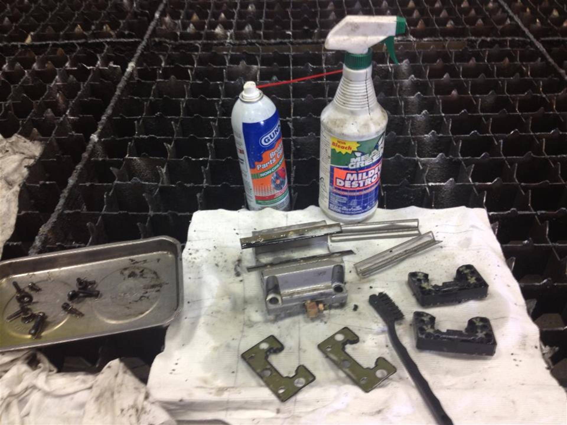
Here is a picture of the Cincinnati Linear Way Guide block, being fully disassembled and cleaned for refurbishment. What Ballscrew Guys have found over the decades of servicing Cincinnati Lasers, is that over time the grease in the Linear Way Guide blocks ends up drying out an hardening. Eventually reaching a point where the grease never fully flows into the bearing systems. There is no substitute to taking these apart and scrubbing all the components with brushes and pipe cleaners.
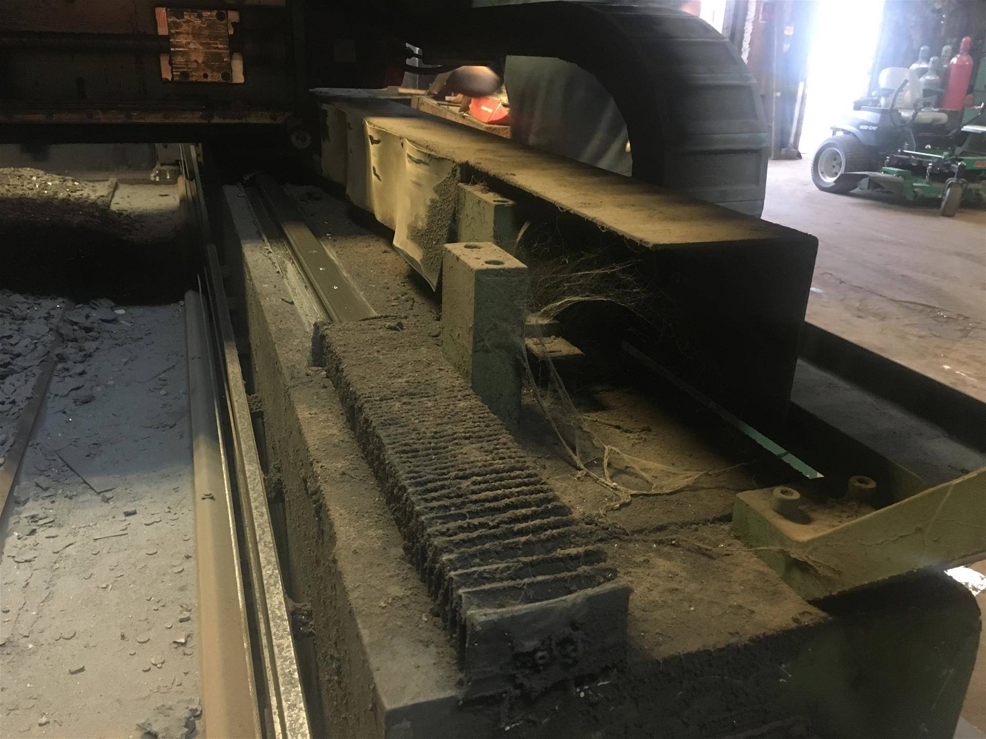
Ballscrew Guys recommending cleaning your Cincinnati Laser at least every decade or so.
With all seriousness though, if your laser looks like this, with damaged covers, Please call us. We can help you with some free suggestions in keeping your equipment running longer, With only a simple investment of your maintenance staff's time and elbow grease. Letting your equipment go to this level can cause irreparable damage to your ball screw and linear motion systems. Cleaning is critical for CNC motion systems.
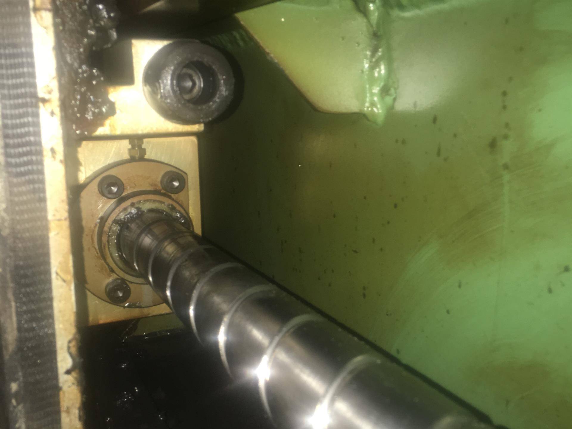
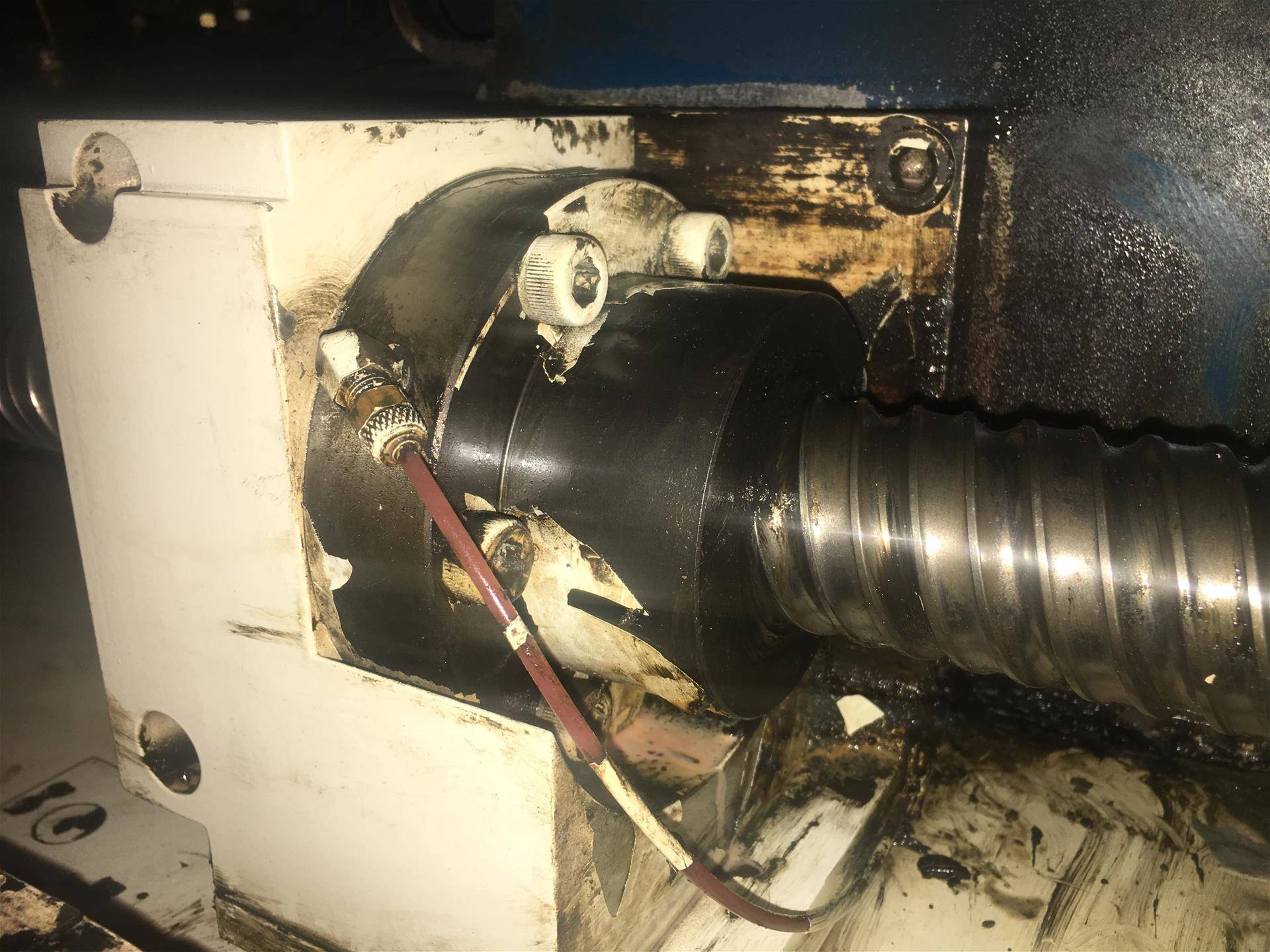
Pulling back the covers on a CL-7a Cincinnati Laser as part of the Y-Axis Ball Screw Repair. Can you see the problem regarding its premature wearing out? Look at the ball screw shaft. It's clean. Notice the small amount of grease where the ball nut seal meets the screw shaft. Only a few clumps of solidified grease. See the brass fitting sticking straight up out of the flange? That is a lubrication line fitting. The lube line clearly was snagged or damaged somehow. Needs to be replaced. With Ballscrew Guys, it's one thing to tighten up the machine and tweak you older equipment to make accurate cuts. But You cannot ignore what caused your system to wear in the first place.
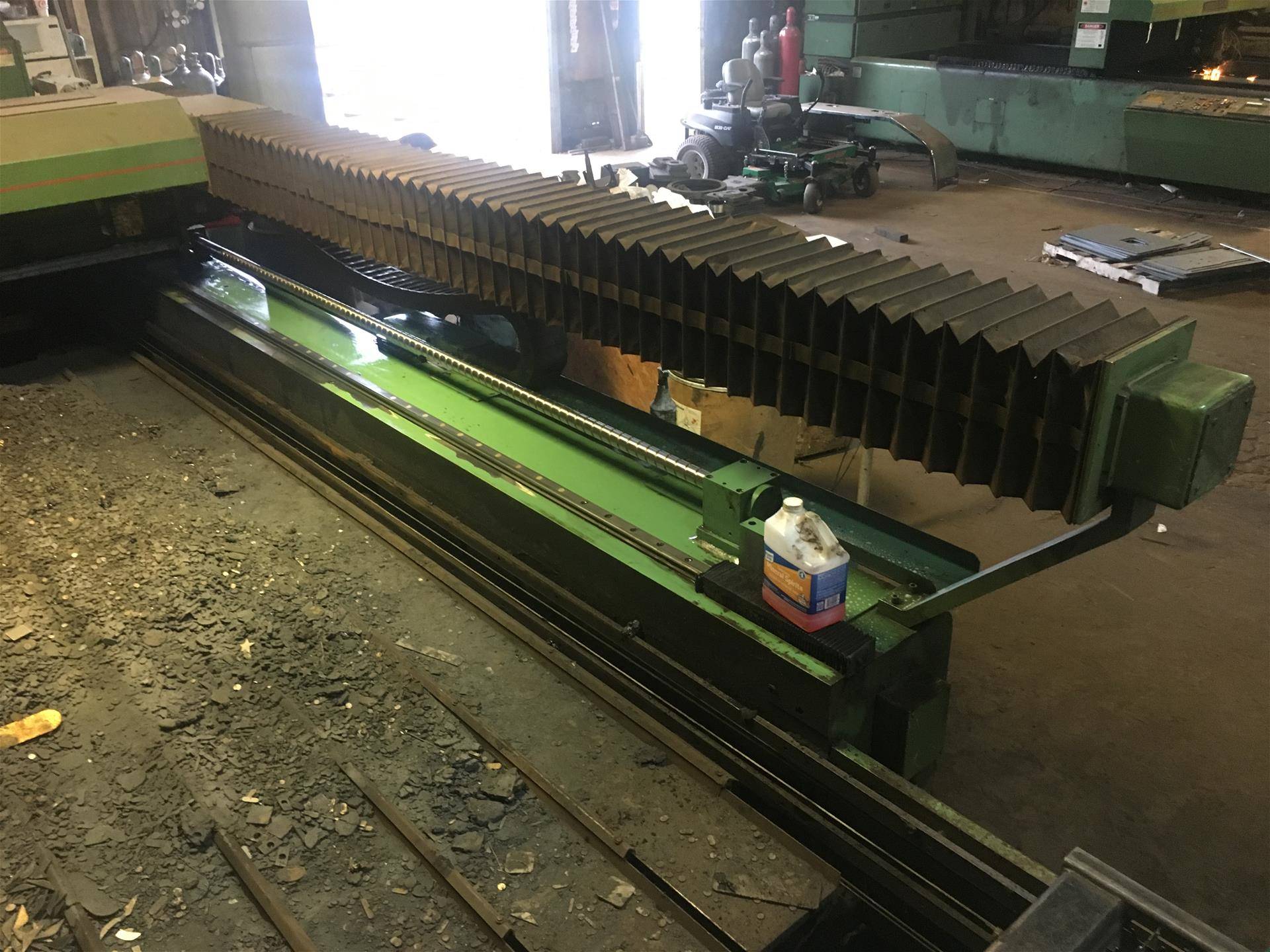
This is the Cobwebs Machine shown earlier. This photo is during the X-Axis motion system cleaning and inspection part of our service. The only way to evaluate motion systems problems is to go through every millimeter of your ball screw assemblies and linear motion rails. They must be cleaned prior to service, so we do it.
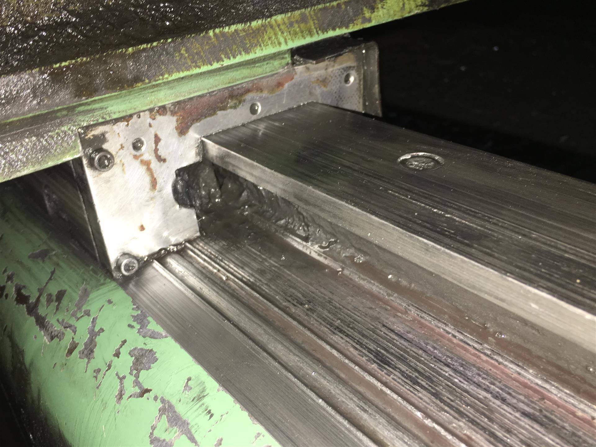
The accuracy and positioning of the entire Y-Axis laser Gantry of the Cincinnati Lasers are based on the X-Axis Ball Screw and the Linear Motion Rail located near that ball screw. The end of the gantry near the operator's terminal is essentially a simple roller with grease fittings. Grease fittings which often get ignored, because they are hidden from view. This image shows almost a decade of damage done to a CL-7a by a failed roller. The roller inside ended up binding and failing. The machine was kept in production for years after. Wearing the roller out of it, then later carving a 1/4" deep gouge all along the X-Axis. What is great, is even with a rebuilt ball screw and linear way guide rail, we got them cutting round holes again. Greasing up this assembly as a simple slide rail bought time till a new roller could arrive. A short term fix. If left undone, the bearing components we refurbished would wear out in months.
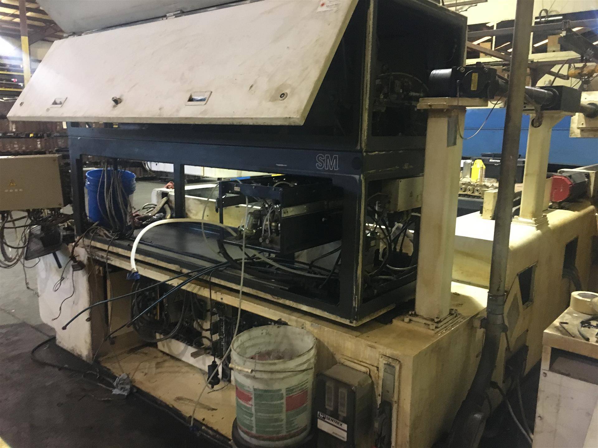
Ballscrew Guys often works with other service technicians, Coordinating repairs to your equipment to keep downtime to a minimum. We have extensive contacts in the CNC Service Technician world and can also help you find quality help solving your machine issues without having to deal with OEM Services and their pricing.
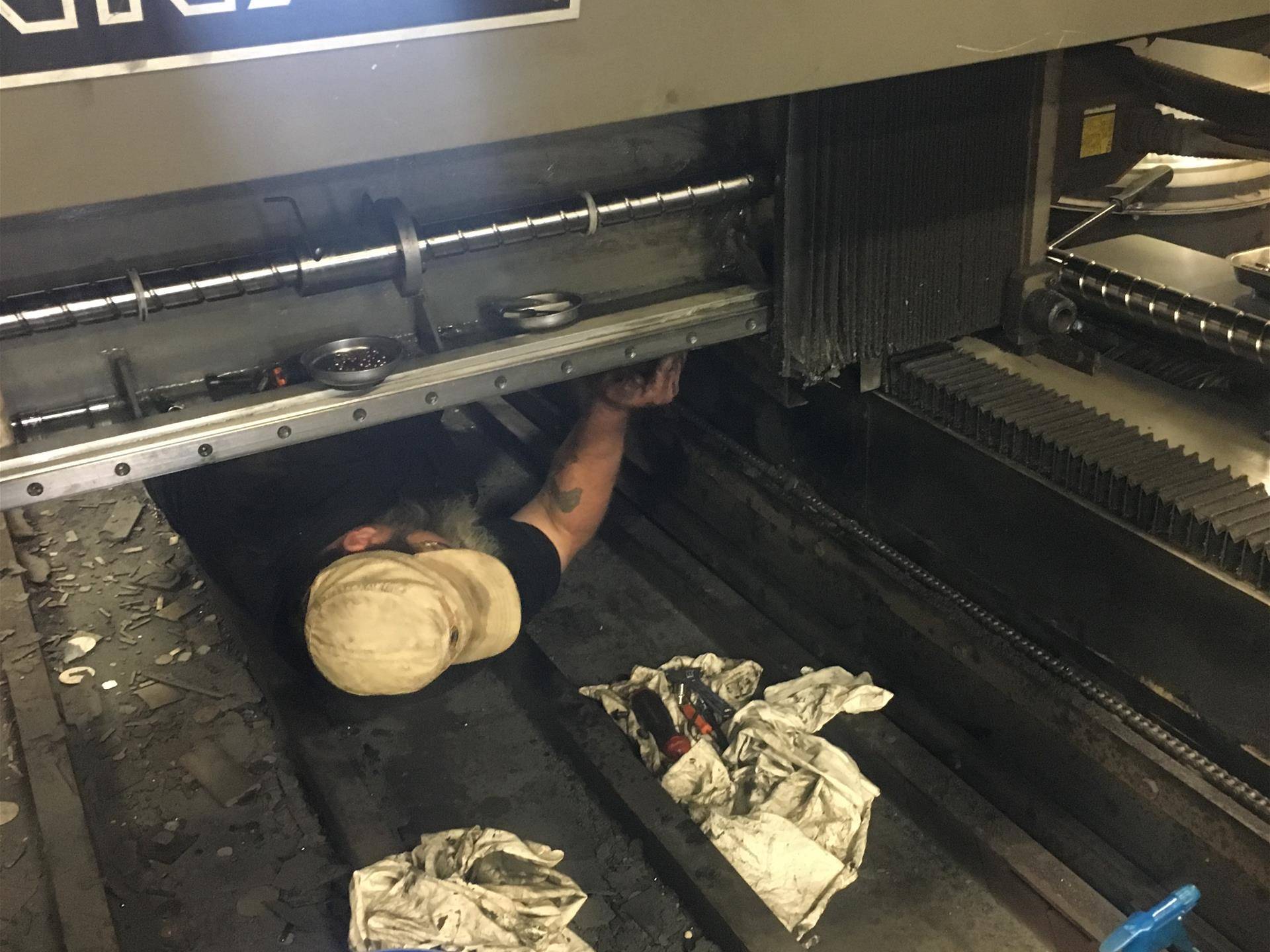
One of the common failures we find in the Cincinnati X-Axis Motion System is lubrication line damage on the Linear Way Guide Sliders or Blocks. These are located underneath the Y-Axis Laser Gantry, and often need to be replaced or repaired.
The most common ball screws found on the Cincinnati CL-series of Lasers is the Japanese manufactured NSK type. Some models however are outfitted with RBC Screws or in this case, a STAR Ball Screw. These STAR Ball Screws are often identified by their unique Ball Screw Shaft windings and races. These Ball Screws are rather unusual, because they have a tension bolt on the side of the ball nut. Allowing the user to manually adjust and tighten the ball nut on the shaft. A word of caution however. If the bearings inside are already worn, the crushing force of this compression bolt can sometimes cause the ball bearings to shatter after hours of machine service time. It is of vital importance that this bolt only be tightened if you have verified that the bearings inside are in good shape and well lubricated. Ballscrew Guys will typically rebuild this entire assembly and refurbish it with fresh oversized ball bearings regardless, as we have too often responded to Cincinnati Laser service calls concerning STAR screws which have failed. These ball screw types are more labor intensive to refurbish, plus require more disassembly to fix properly. This might entail a slight up charge regarding our flat rate pricing.
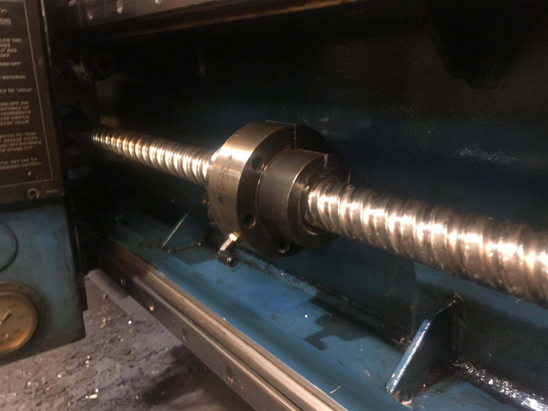
German STAR Ballscrew on a Y-Axis. This is a ball nut which has a tension bolt that allows the operator to adjust out some looseness in the screw as the bearings wear. Still, this design has its limits. We at Ballscrew Guys have encounters ball nuts which have been crushed and cracked because the bolt has been cranked tight one to many times. This system works well if the ball nut is kept clean and well lubricated, with bearings in good condition. But, if the bearings are worn, sometimes the bolt adjustment can just be the final force smashing the bearings, causing the screw to lock up.
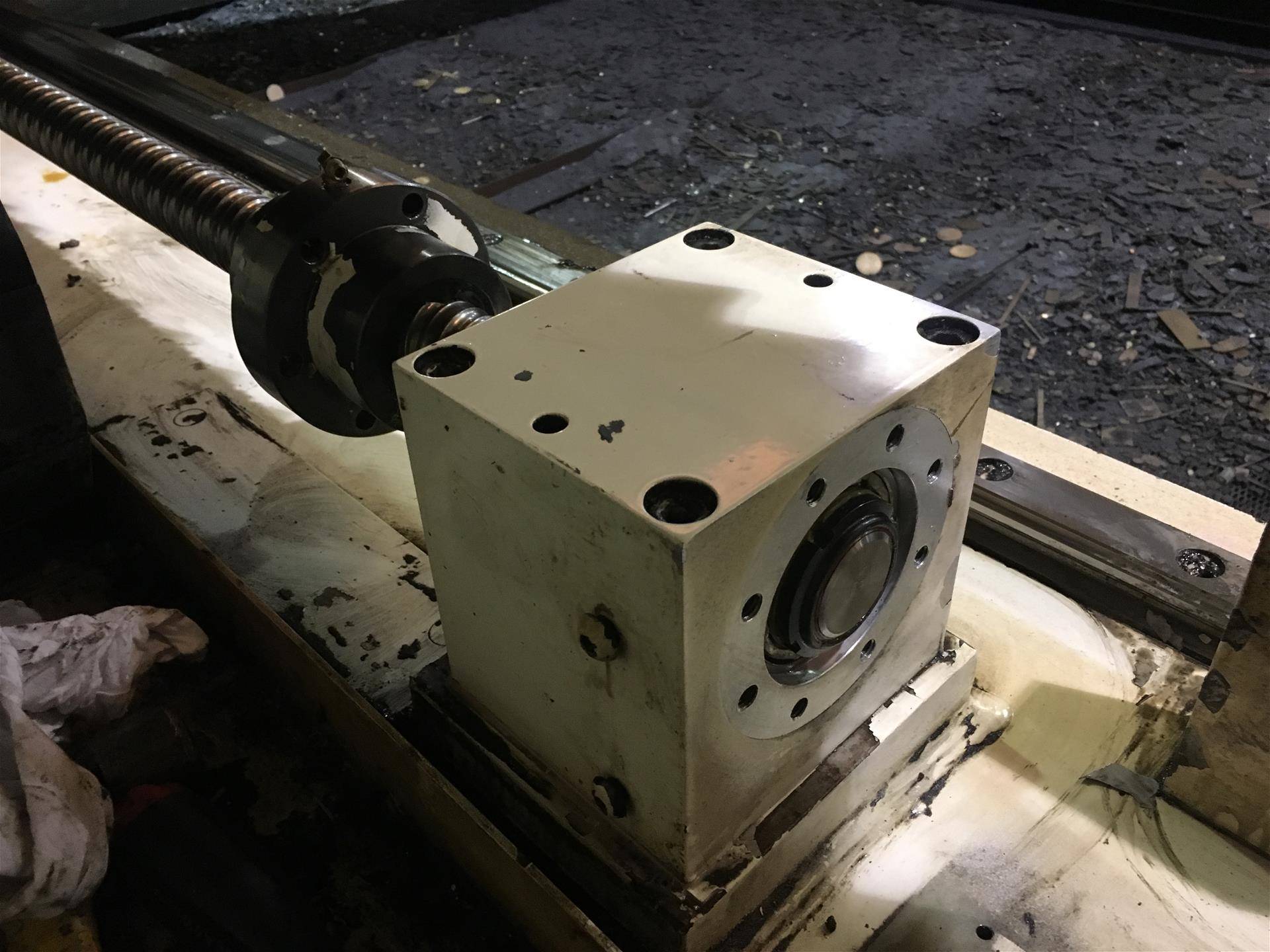
To adequately refurbish the STAR ball nut, it has to be wound off the end of the ball screw. This means that the end bearing assembly at the end of the screw shaft has to be disassembled and removed. One of the reasons why STAR Ball Screw Service on your Cincinnati Laser might be slightly more expensive than our regular NSK based screw Flat Rate Pricing. The end Bearing housing and limit switches have to come off. Then be replaced properly. Because this work must be done, we always do End Bearing service, cleaning and lubrication at this time. As the parts are exposed and available.
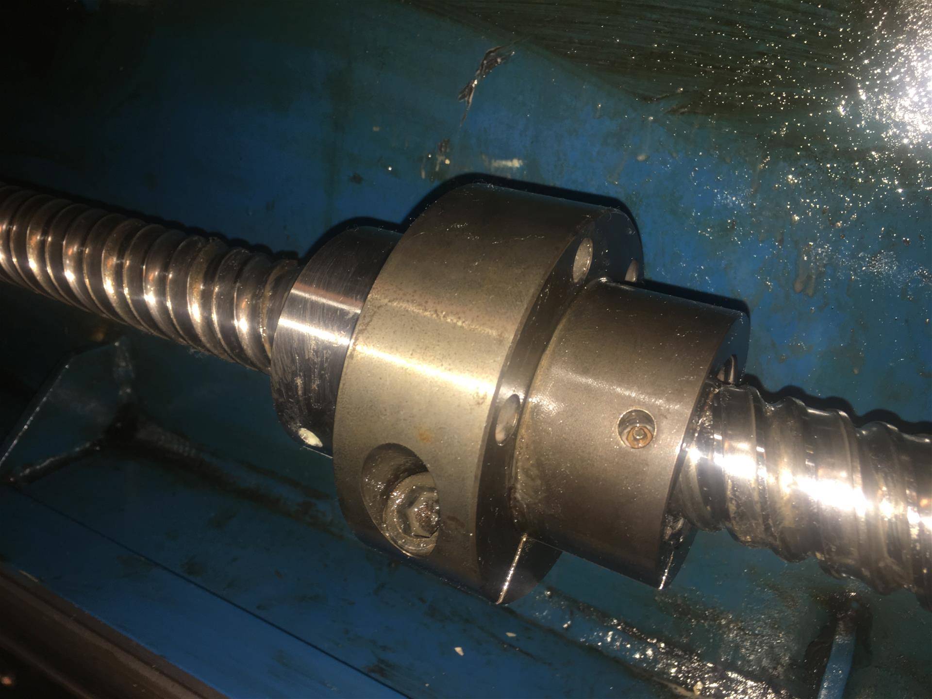
The Allen Hex Adjustment Bolt on the STAR ball screw nut. While deceptively simple in concept, be cautious of cranking down on this. Excessive tightening can crush bearing balls or crack the ball nut housing.
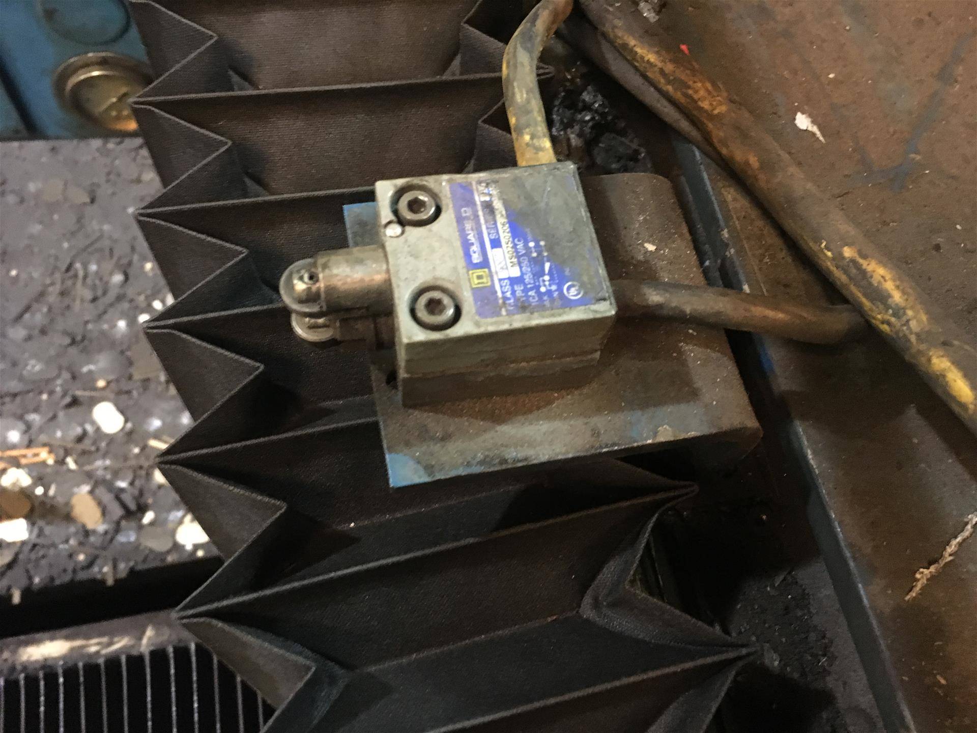
Underneath the Y-Axis top cover, hidden behind the Y-Axis bellow covers are the limit switches. Typically there are two switches mounted to one single bracket. Over time, these brackets sometimes get bumped out of position. Or get coated and clogged with grease, dirt, and debris. These do need to be periodically cleaned out and tightened down. This picture was taken when we were trying to hunt down an mysterious Y-Axis overtravel alarm. Turns out, only one of the two connecting bolts were installed. Causing the entire limit switch assembly to flop around like a hinge.
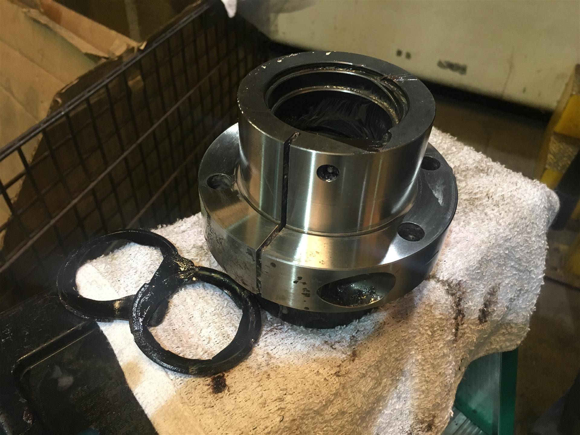
Cleaning the ball nut out and inspecting seal condition. Ballscrew Guys can create and replace hard to find and discontinued seals.
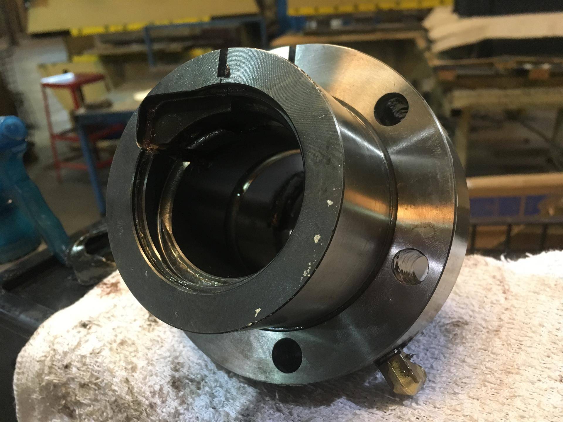
The STAR Ball Screw Nut Bearing Recirculation Plug Design is common on European manufactured ball screw systems. Seeing that JBL, STAR, and Rexroth have a common heritage over the years, it's not surprising to find the same design concepts in all of their ball screws. The Bearing Recirculation Plugs found in this STAR ball screw nut is made from plastic, but is way more massive and stout as compared to the Bosch-Rexroth inserts.
